Main Page|Introduction|Frame|Vehicle Dynamics|Aerodynamics|Testing|Who did it?
Aerodynamics
Due to the variety of constraints imposed on thunder design regarding the speed, safety and frame design, the improvement approach in aerodynamic design was followed. The main objective was to fit the existing non-aerodynamic components (frame and drive train) inside an aerodynamic fairing, made out of a light material.
The conceptual design rests upon three characteristic features which are:
1. Top View Streamlining using a NACA-6 series airfoil function
2. Front view composed of half ellipses
3. Asymmetric side view of acceptable aerodynamic profile to avoid negative lift in case of using a symmetric side view due to the near ground effect (aerodynamic interference)
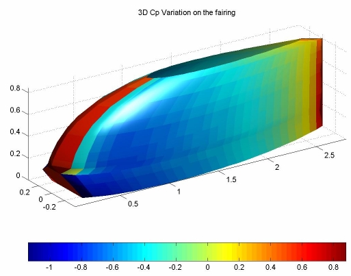
Aerodynamic analysis using two different computational fluid dynamics techniques (doublet strength distribution method & source (vortex) panel technique) was carried out, and several iterations led to the existing profile. Conceptual design, CFD analysis and 3D modeling was carried out on MATLAB. The CFD codes are based on the Kuethe & Chow codes for the aforementioned techniques.
Glass fiber reinforced plastic (GFRP) was used to manufacture a light, rigid and durable fairing. A male mold was made out of wood, Styrofoam and gypsum. Hand lay up method was used to produce the final fairing. The produced composite was made of fiberglass reinforced polyester.
Main Page|Introduction|Frame|Vehicle Dynamics|Aerodynamics|Testing|Who did it?